CAD Surface Position and Orientation
Introduction
When FRED imports a CAD model, all of its surfaces are defined by NURBs, or trimmed versions of those NURBs called Trimmed Parametrics. These parametric surfaces are always defined in the global coordinate system. One of the major difficulties with this definition is that the X, Y, Z location of a surface is not easily determined from the parametric definitions, which makes the alignment of these structures with native FRED objects difficult. For more information about CAD coordinate systems, see our related article: Attaching Entities to CAD Surfaces
The script that accompanies this document identifies the position of a surface in global coordinates by using numerical sampling with rays. A source is created on the selected surface and the ray statistics are retrieved to give average position and surface normal direction in the global coordinate system. Knowing the position and direction of the surface normal is usually enough information to properly align the NURB objects in a FRED model.
Running the Script
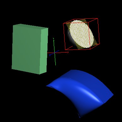
After opening the accompanying FRED file you will see the following 3D view.
If we wish to identify the location and orientation of the flat, grey surface in the model, we should take the following steps:
In the 3D view, double mouse click on the surface of interest. This will open the surface dialog and also highlight the node on the object tree.
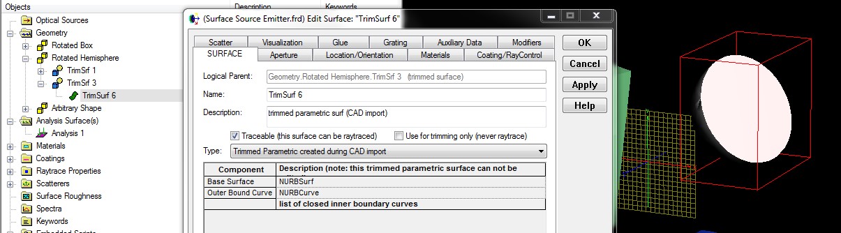
Now we can see that our surface of interest is “TrimSurf 6”. Hover your mouse over the green-wavy icon on the tree for this surface to reveal the tooltip.
From the tooltip, we see that this particular surface is node number 23, which is indicated in the tooltip on the first line, “[23] TrimmedParametric”. Expand the Embedded Scripts folder to reveal the script called “Find Surface Location”, then right mouse click on the script node and select “Run an Embedded Script” from the context menu. The script has been written so that a user interface is opened when the script is executed. The user interface dialog is shown below.
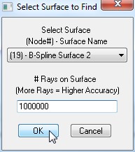
Using the drop down list, select surface 23 and then in the text entry area enter a value of 10 million.
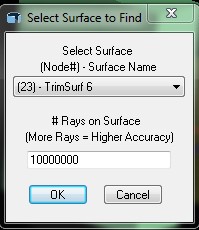
Press the OK button and then wait for the calculation to be performed (the status bar at the bottom of your FRED window will be displaying information). When the calculation has finished, the output window will contain the following information.
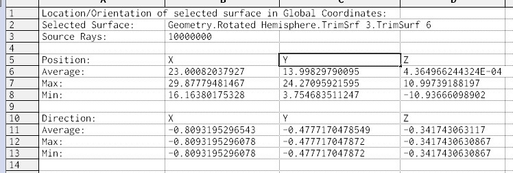
The output of the script tells us that the surface is located at (x,y,z) = (23.000, 13.998, 0.000) in global coordinates and its surface normal is pointed in the direction (a,b,c) = (-0.809, -0.478, -0.342).
Applying the Output
What do we do with this information?
Suppose that we want to take the analysis surface in the FRED file and “assign” it to TrimSurf 6? We would take the following steps:
Open up the dialog for “Analysis 1” in the Analysis Surfaces folder. Right mouse click in the location list and Append a new operation.
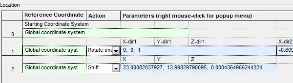
Change the operation type for the new operation from “Shift” to “Rotate one direction to another”. The intention is to rotate the analysis surface from its current orientation to the same orientation as TrimSurf 6. We take the average ray direction from our script output and enter it into the second vector direction for our new operation.

Right mouse click in the operation list and append another operation. Enter the average ray position calculated by the script as the Shift values.
Now, hit Apply on the dialog and check the 3D view. You should see that the analysis surface lies in plane with TrimSurf 6.
After positioning the analysis surface using the script output, the only thing left to do is make sure that the Ray Selection criteria is properly set on the analysis surface.
Closing Remarks
This article has demonstrated a method for using FRED’s scripting language to implement a custom interface that allows numerical determination of a surface’s global position and surface normal orientation. While the script is primarily intended to be used on imported CAD objects, whose surfaces do not have usable local coordinate systems, it will work on any surface type.
Download the FRED Script: calculateSurfacePositionOrientation.frs
Download the FRED file: Surface-Source-Emitter.frd


